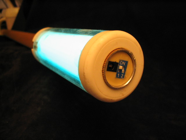
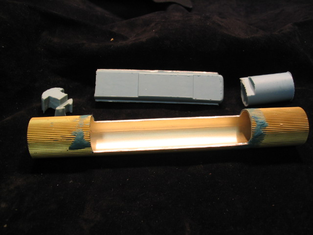
 One staff end. Note the charging receptical (so you don't have to tear it apart to change
batteries) and the power switch.
One staff end. Note the charging receptical (so you don't have to tear it apart to change
batteries) and the power switch.
One staff end. Note the charging receptical (so you don't have to tear it apart to change
batteries) and the power switch.
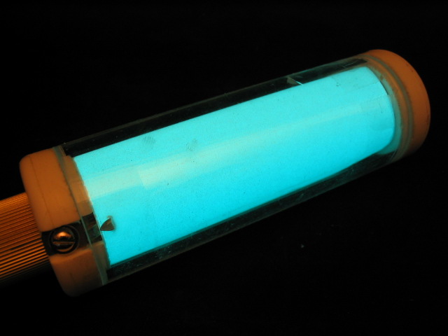 The staff glowing.
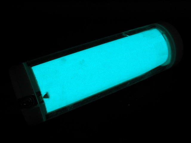 The staff glowing in the dark.
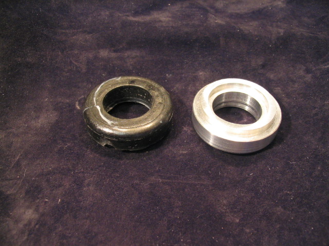 Two of the lamp end caps. One (left) cast in resin and the other (right) machined in aluminum.
 Another view.
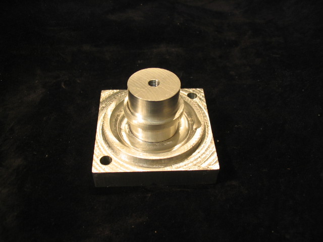
 The four part mold the end caps are cast from. It's machined out of amuluminum. Because of
the end cap's shape, a four part mold was required so that the part could be removed. This
mold was successfull but problematic. Using a a mold made out of aluminum (or any ridgid
material for that matter) is a good/bad thing. It gives you great precission and incredible
finishes (assuming you gave the mold a great finish). However some casting resins can also
double as a "metal adheasives." That overcome, if you remove the part too soon it's got "give"
which makes it somewhat "sticky" and prone to distorting and marring. If you remove the part
too late it will have fully hardened and then you'll be prying one unyiedlting part from
another. Finding that middle ground "sweet spot" takes some doing.
The four part mold the end caps are cast from. It's machined out of amuluminum. Because of
the end cap's shape, a four part mold was required so that the part could be removed. This
mold was successfull but problematic. Using a a mold made out of aluminum (or any ridgid
material for that matter) is a good/bad thing. It gives you great precission and incredible
finishes (assuming you gave the mold a great finish). However some casting resins can also
double as a "metal adheasives." That overcome, if you remove the part too soon it's got "give"
which makes it somewhat "sticky" and prone to distorting and marring. If you remove the part
too late it will have fully hardened and then you'll be prying one unyiedlting part from
another. Finding that middle ground "sweet spot" takes some doing.
 Two of four parts.
 Three of four parts.
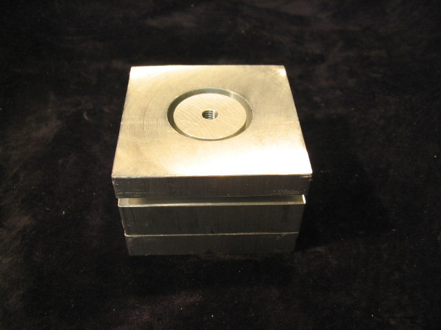 Ready to go! Actually, the mold is "ready to go" when the first three parts are fastened to
each other. Then the pour is made and the fourth part is dropped carefully into place.
Getting rid of air bubbles, alas, is tricky at best.
Ready to go! Actually, the mold is "ready to go" when the first three parts are fastened to
each other. Then the pour is made and the fourth part is dropped carefully into place.
Getting rid of air bubbles, alas, is tricky at best.
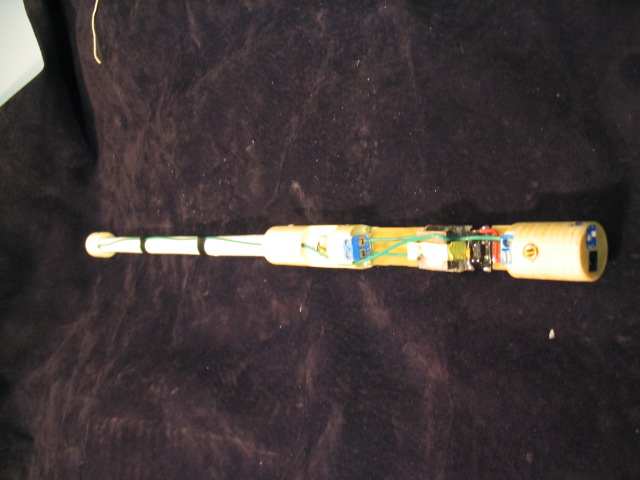 The "power core." Somewhat more complex as a prototype than it would otherwise need to be.
This configuration allows the inverter to be easily checked/fixed/replaced/redesigned.
The "power core." Somewhat more complex as a prototype than it would otherwise need to be.
This configuration allows the inverter to be easily checked/fixed/replaced/redesigned.
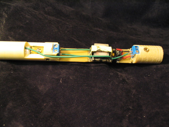 A close up.
 The first step in building a core: cast the body around a brass backbone. The backbone
provide both mechanical strength in what little space is left around the inverter and it
provides one electrical path for the batteries.
The first step in building a core: cast the body around a brass backbone. The backbone
provide both mechanical strength in what little space is left around the inverter and it
provides one electrical path for the batteries.
 This is the mold the body is made from. It's is a hybrid, part aluminum and part silicone.
The silicone parts were, themselves, cast off an original master part that was rough cast in
the aluminum (to get the radius right) and then "machined" with a deremel router bit
in a drill press and a clunky X-Y table.
This is the mold the body is made from. It's is a hybrid, part aluminum and part silicone.
The silicone parts were, themselves, cast off an original master part that was rough cast in
the aluminum (to get the radius right) and then "machined" with a deremel router bit
in a drill press and a clunky X-Y table.
 The second step to building a core: the low voltage board is added and then cast to the
inside diamiter of the tube. This board contains the battery power terminals, the charging
connector and the power switch.
The second step to building a core: the low voltage board is added and then cast to the
inside diamiter of the tube. This board contains the battery power terminals, the charging
connector and the power switch.
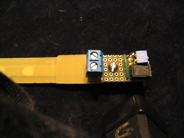 A close up. Note this this board is bolted to the back bone. This is done for several reasons.
It provided a solid mechanical link and it raises the board to the right height so the power
connector and switch are centered at the end of the tube. (See the first photo.)
A close up. Note this this board is bolted to the back bone. This is done for several reasons.
It provided a solid mechanical link and it raises the board to the right height so the power
connector and switch are centered at the end of the tube. (See the first photo.)
 Here the screw is covered by (and positions) a spacer that, in turn, positions a threaded
brass insert. After this end is cast, the insert is what will anchor the core in the tube.
The master for this spacer is the first thing I ever machined on my Sherline mill.
Here the screw is covered by (and positions) a spacer that, in turn, positions a threaded
brass insert. After this end is cast, the insert is what will anchor the core in the tube.
The master for this spacer is the first thing I ever machined on my Sherline mill.
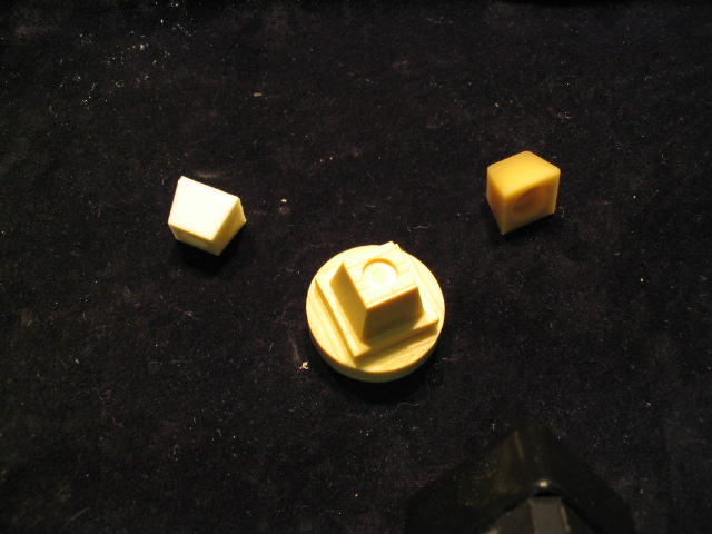 Here is the master spacer's master. It started off as a scrap round from a sample tube
casting. Then I machined it into a square and then finally into the "pyramid" shape. I wanted
the pyramid shape to make it easier to extract fromt he mold, but I needed the square base
to hold it for machining.
Here is the master spacer's master. It started off as a scrap round from a sample tube
casting. Then I machined it into a square and then finally into the "pyramid" shape. I wanted
the pyramid shape to make it easier to extract fromt he mold, but I needed the square base
to hold it for machining.
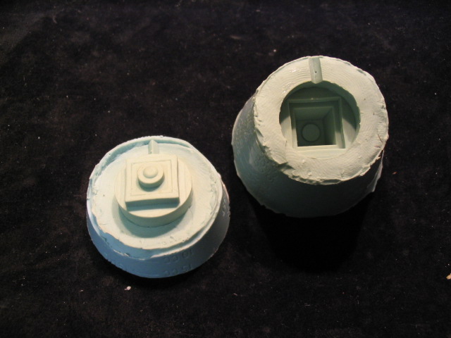 This is the mold that makes the spacers. It was my first attempt at a silicone mold, not
too bad all things considered. It was made it two passes. First the bottom was made from
the original pyramid-square-round master. Then a duplicate of that was made and
the final master was machined from it. Finally the master was placed in the mold and the
top silicone pour was made. Learned a valuable lesson in how to avoid parting line problems:
when you can, use two masters, one oversized and one spot on, to make molds that are
practically parting line free.
This is the mold that makes the spacers. It was my first attempt at a silicone mold, not
too bad all things considered. It was made it two passes. First the bottom was made from
the original pyramid-square-round master. Then a duplicate of that was made and
the final master was machined from it. Finally the master was placed in the mold and the
top silicone pour was made. Learned a valuable lesson in how to avoid parting line problems:
when you can, use two masters, one oversized and one spot on, to make molds that are
practically parting line free.